By Aaron Mazeika, P.E., S.E., MIStructE, AIA, LEED AP, M.ASCE
Known as Chicago’s smartest building, 800 Fulton Market brings a post-pandemic office typology to the city’s vibrant Fulton Market District. Packed with amenities and building management technologies to maximize the tenant experience, the smart building moniker also applies to the structural engineering of its innovative exterior bracing system, which flexes to accommodate Chicago’s harsh thermal environment.
The design priorities established in 2018 by global property developer Thor Equities Group for 800 Fulton Market proved highly fortuitous for the post-pandemic workplace. Set in the heart of downtown Chicago, the 19-story multiuse space has private and commercial floors in addition to spaces for the public.
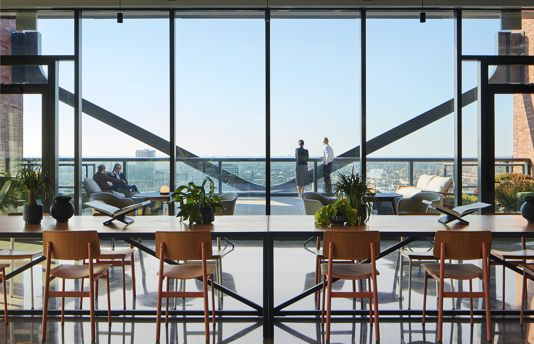
The building includes a vast array of tenant amenities, such as a state-of-the-art fitness center, bicycle parking and repair services, a fleet of electric scooters, electric vehicle charging stations, a lobby cafe and restaurant, over 6,000 sq ft of conference facilities, a penthouse lounge, and a terraced roof deck.
Additionally, more than 50% of the building’s roof is dedicated green space.
A smart building
The embodiment of smart technology, 800 Fulton Market is one of the first smart buildings in Chicago. The building incorporates a suite of high-tech mechanical systems that improve the building’s energy efficiency and the comfort of its tenants. These systems include sensor technologies that monitor and communicate building metrics to management and tenants, from building occupancy to space utilization.
The 800 Fulton Market smartphone app VTS Rise handles conference space bookings, centralizes tenant communications, and allows building management to control access to the building and disseminate vital information about the building to tenants.
Variable air volume carbon dioxide sensors populate the building, providing real-time readings that regulate ventilation, and indoor air quality sensors relay to building management metrics for temperature, relative humidity, sound level, particulate matter, and more.
The building is certified WELL Gold, Leadership in Energy and Environmental Design Platinum, WiredScore Platinum, and Smart Score Platinum. These certifications were pursued early in the planning phase and display the developer’s commitment to environmental conservation and tenant wellness, especially post-pandemic.
Background and development
The site is just outside the eastern edge of the Fulton-Randolph Market Landmark District and within one of downtown Chicago’s expansion areas. The location and the proposed design presented a unique challenge to the team: how to create an office building of sufficient scale to complement the height and density of the downtown area while also respecting the adjacent lower-rise landmark district.
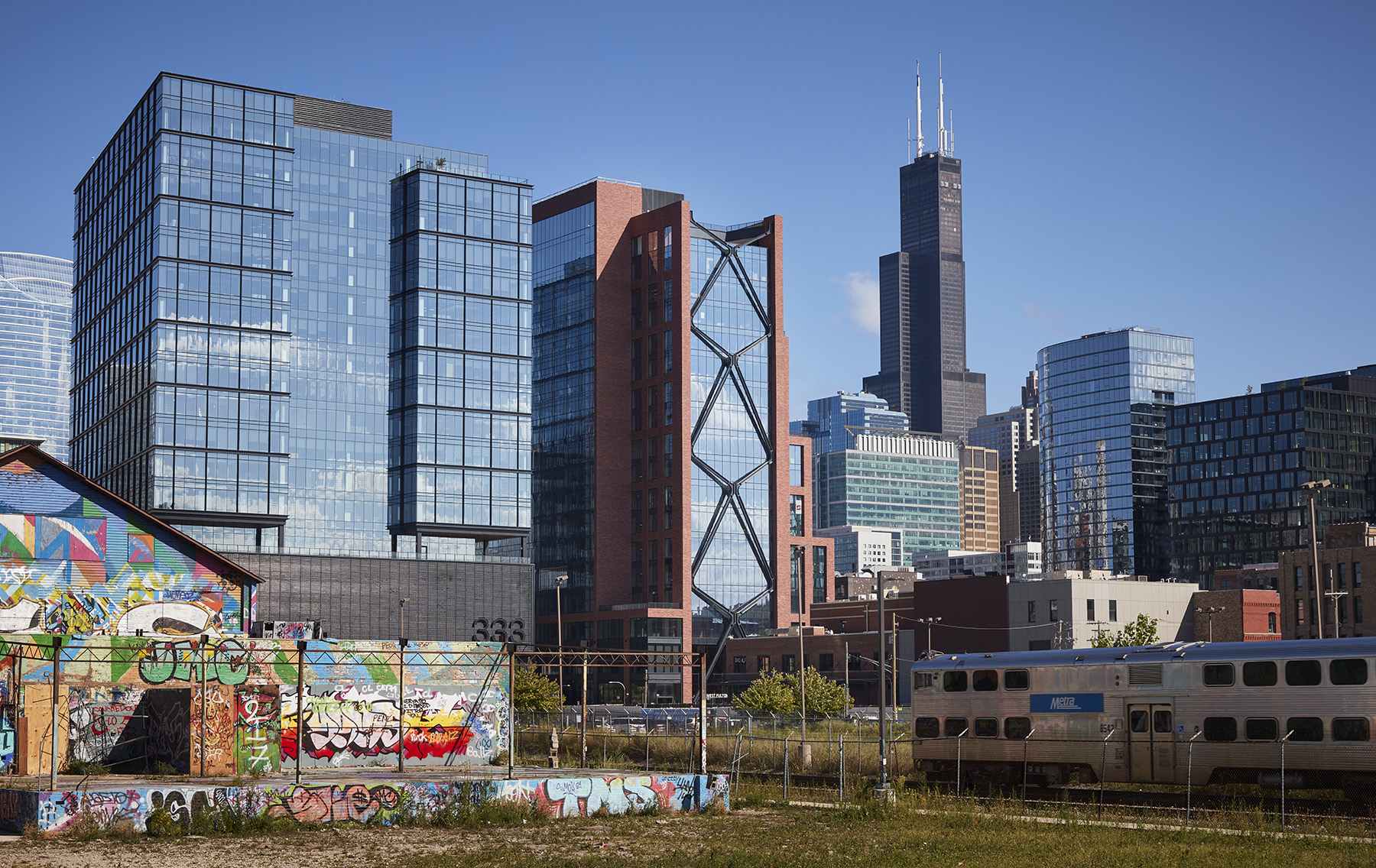
The design team of Skidmore, Owings & Merrill, an architecture and engineering services firm, proposed a full-block amenity podium similar in scale, appearance, and function to the adjacent buildings within the landmark district, placing a rectangular high-rise linear office building at the extreme north end of the site. This approach achieved a scale transition from the high-rise buildings to the north and east to the podium-scale historic buildings to the south and west.
Unexpected concept design
Because of the height and land-use differences between the sides of the building, there was great disparity between the expansive city and neighborhood views to the south and the fully blocked views to the north. The design team resolved this disparity by offsetting the building’s core at the north side and creating uninterrupted, column-free floor plates so all views pointed south.
While office buildings in Chicago typically have structural steel floor framing, because of the building’s atypical 60 ft floor spans, the offset core, and supply chain issues, the design team had to be flexible in its choice of materials.
At the concept design phase, SOM developed a broad range of potential steel and reinforced-concrete structural engineering solutions. SOM collaborated with the developer’s preconstruction manager, Lendlease, a globally integrated real estate group specializing in development, design, construction, and other services. Lendlease evaluated the cost-effectiveness of SOM’s schemes, and unexpectedly, a long-span, posttensioned, reinforced-concrete floor-framing system proved to be the most economical approach.
While this floor-framing system was the most cost-effective gravity-force-resisting system, the lateral wind-force-resisting system also had to be accounted for. The shallow, 24 in. deep, posttensioned beams and 60 ft floor spans made for an ineffective moment-resisting frame, while the narrow offset core was insufficient on its own.
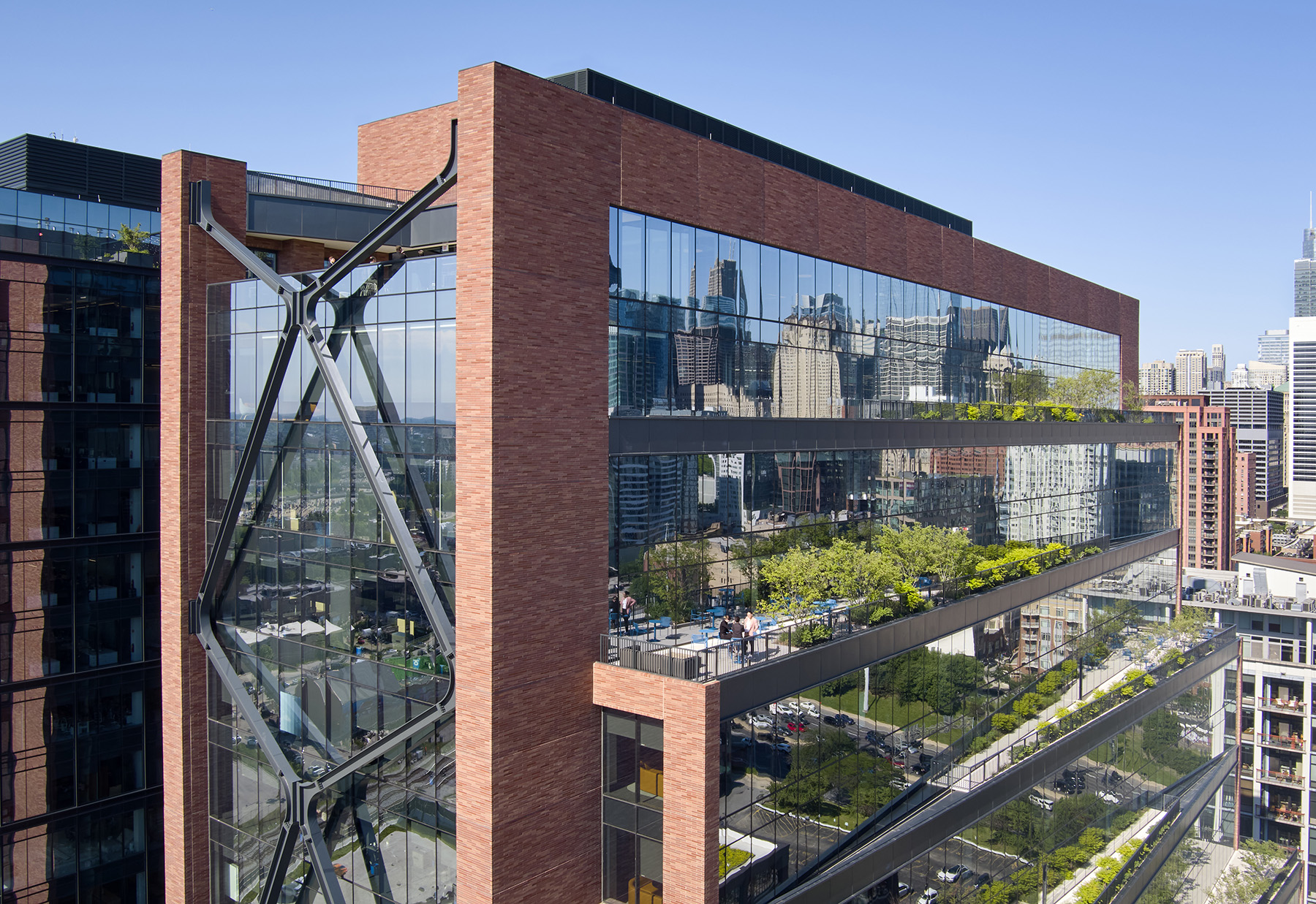
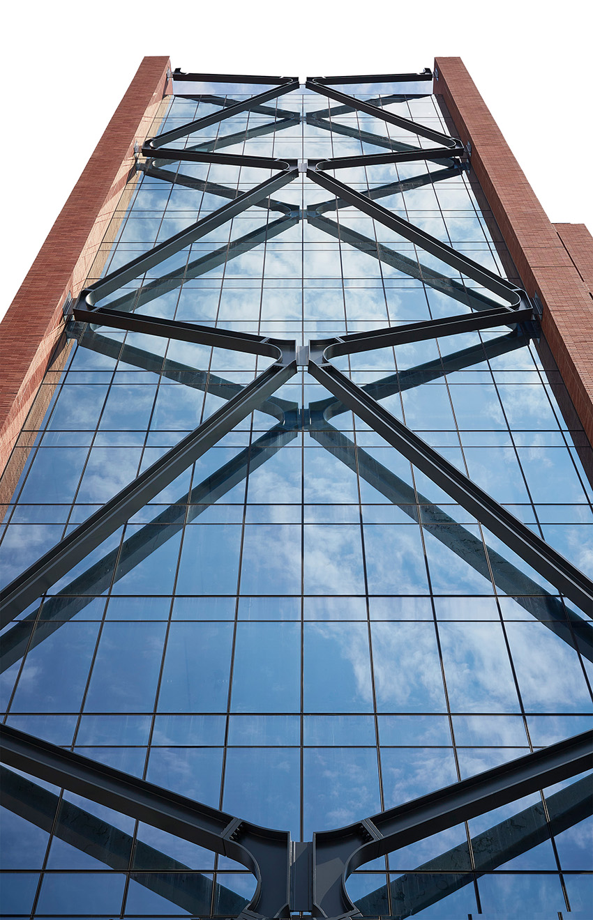
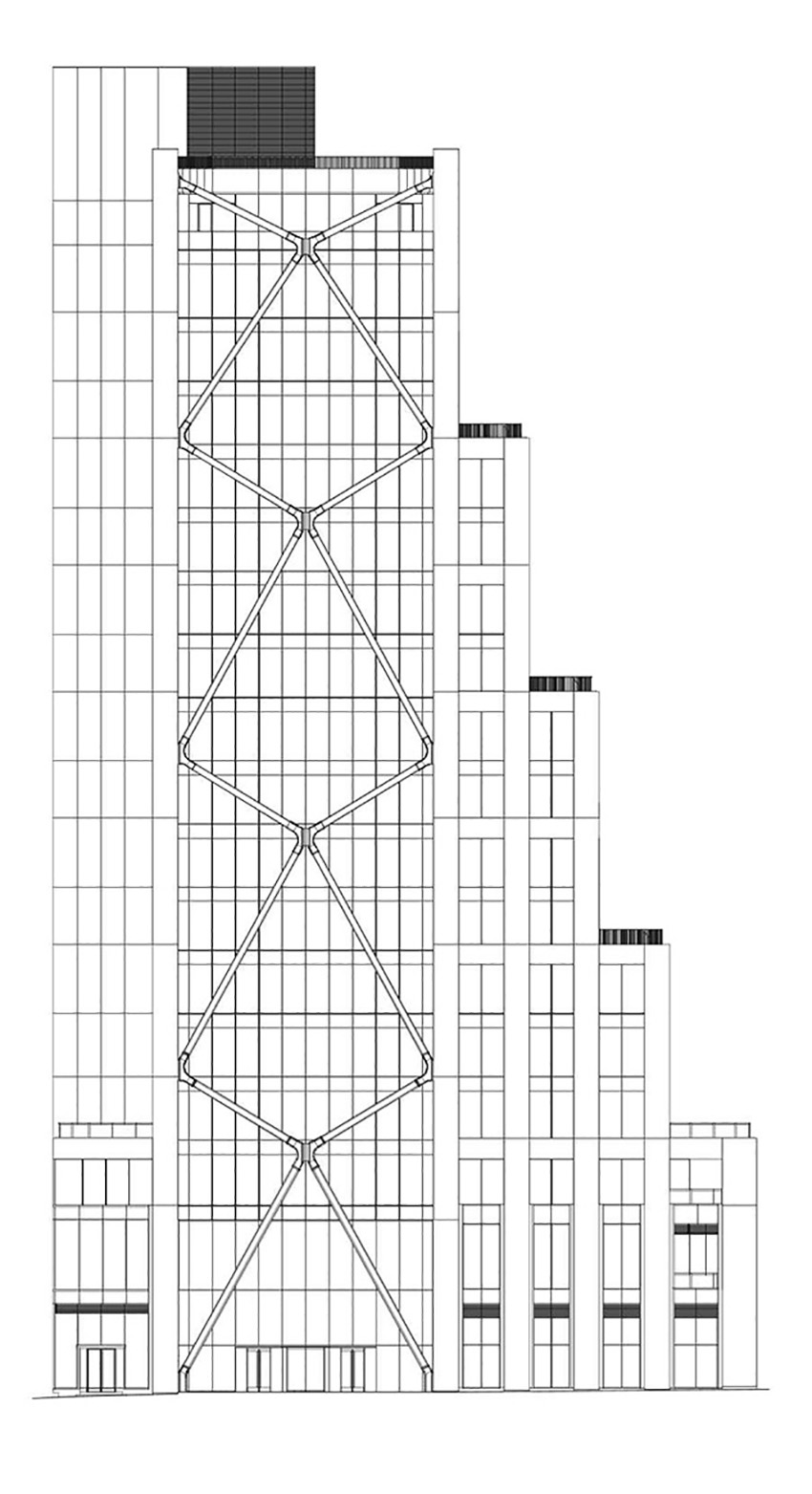
This lack of stiffness in the north-south direction was worsened by the building’s configuration, creating the maximum wind load demand in this direction. To solve this issue, SOM integrated structural steel, exterior-braced frames into the west and east facades of the building. The braced frames provide an efficient method of resisting wind loads by extending the lateral-force-resisting system across the full 60 ft width of the building.
Once the external steel braces were added to the design, the team determined that the steel braces would be able to resist the majority of the wind load demand. This allowed the design team to eliminate all but two of the concrete walls in the building’s core.
These concrete walls distribute the incoming wind loads onto the glass facades on every level and apply these forces to the edge of every floor slab. The braced frames are connected to the building every five floors, called nodal floors, so the reinforced walls in the core are used to collect the wind loads from every floor slab and transfer them to the nodal floors where they can then be transferred to the braced frames. These walls also serve as a redundant system and backup to the braces.
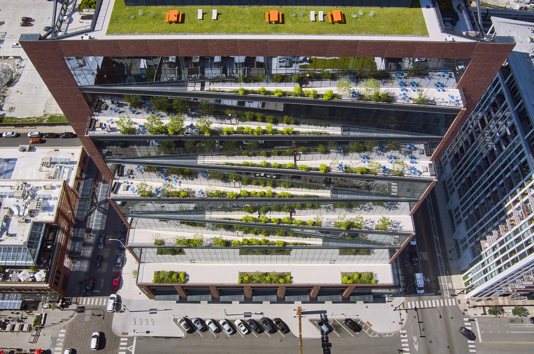
The design team had also determined during the concept design phase that a series of cantilevered terraces on the south side of the building could help the structural system’s efficiency by providing a balanced cantilever that would reduce the deflections of the main 60 ft spans. With the majority of the core walls eliminated, the architectural core components on the north side of the building could be similarly cantilevered, further balancing the deflections of the main spans.
The absence of most of the concrete walls in the core enabled a fully glazed facade on the north side of the core, illuminating the elevator lobbies, bathrooms, and exit stairs — all of which enhance the tenant experience.
Solution-focused execution
As engineers, we typically use the materials that are best suited for the load each component demands. Columns and walls typically resist high-gravity forces and are subjected to permanent compression loads, and reinforced concrete is extremely cost-effective as a material for resisting compression loads.
For the building’s brace diagonals, SOM’s design anticipated tension and compression forces that were equal in magnitude and reversible because the wind could blow from any direction. SOM determined that reinforced concrete would be impractical for resisting the high tension forces in the braces. Instead, the team opted for structural steel members, as they have similar tension and compression properties.
The combination of materials used for this project presented some difficulty. When steel braces are connected to reinforced-concrete columns, there is a tendency for the concrete to creep. If conventionally detailed, the steel braces can act as a secondary gravity load path, and as the concrete creeps, the steel begins to carry a portion of the column gravity load. This process can be detrimental if the goal is to limit the size of the brace members.
The design team also carefully considered the locations of the braces with respect to the facade line. The team chose to locate the braces inside the facade line. This novel placement solved the potential issue of parallel load paths, creep in the columns, and thermal loading of the braces. This placement also simplified the interior planning and facade detailing but added complexity to the structural design of the braces subjected to thermal loading.
By introducing a 24 in. out-of-plane eccentricity at the central crossing nodes of the braces, the brace diagonals formed the edges of a shallow pyramid — a configuration that decouples the strains in the vertical columns from the strains in the braces when subjected to symmetrical loads.
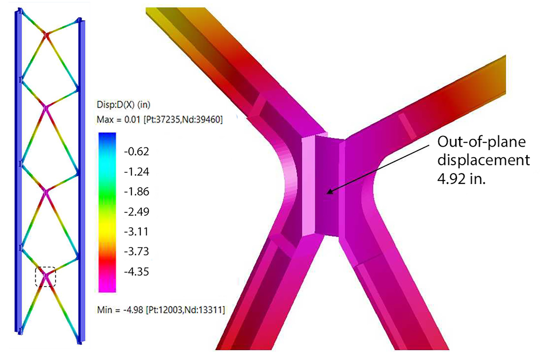
When the braces are subjected to increased temperature due to solar heating, they lengthen, but the central crossing node simply moves further away from the facade, forming a slightly taller pyramid. As the braces lengthen, the geometry adapts, and no internal force is induced in them. Similarly, when the columns shorten due to creep or superimposed gravity loads, the central crossing nodes move away from the facade and the columns shorten with no load transferred to the braces.
When subjected to asymmetric loads, such as lateral wind loads applied to the building, equal and opposite tension and compression loads are induced in the braces. The tension and compression forces provide out-of-plane stability to the central crossing nodes, and the braces are fully effective at resisting wind loads through a full range of eccentricities of the central nodes. In the full design temperature range of the structural steel bracing system, the central node can move 5 in. inward or outward from its initial position.
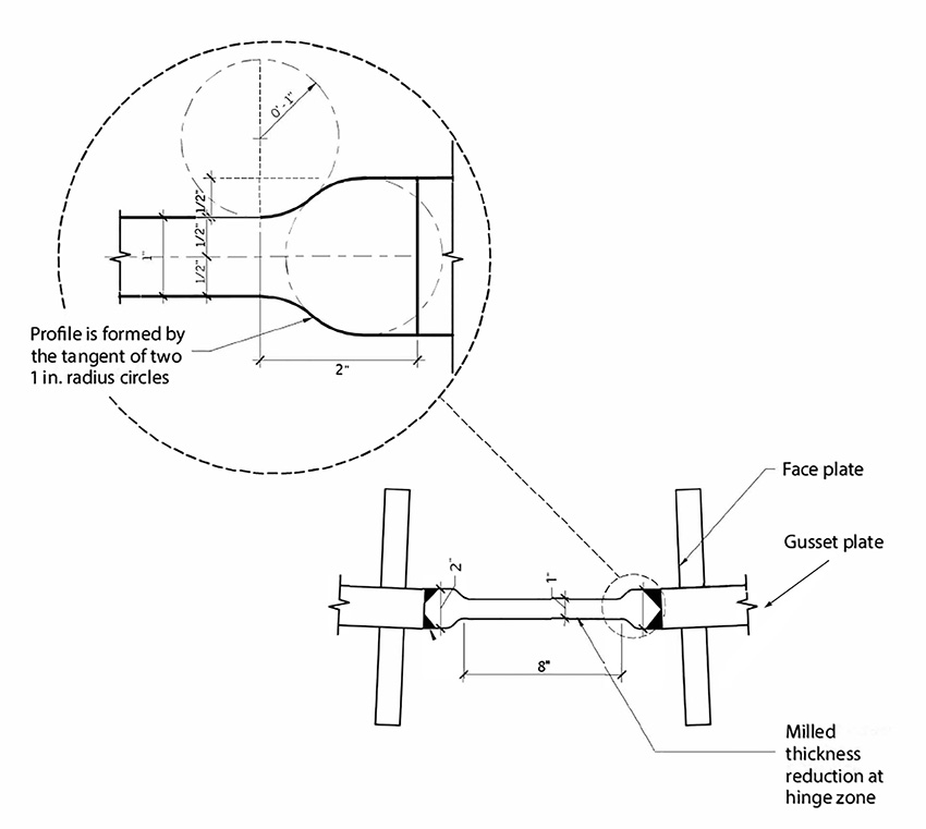
The SOM team designed and detailed the brace nodes, employing a similar performance-based approach. In order for the central nodes to move freely without inducing stresses in the braces, the central nodes and side nodes had to hinge along a vertical axis. SOM contemplated a door-hinge-type detail, but it determined that elastic flexural hinging plates would achieve the required flexibility with fewer future maintenance concerns.
The team modified the height, length, thickness, and material properties of the hinging plates to meet design specifications. To reduce fatigue, the hinging plates were machined to a dog bone profile from a thicker plate, allowing all welding to be performed at the point where stresses were greatly reduced. The hinging plates are made from high-strength, low-temperature, high-ductility material typically used in bridge construction.
The curved profiles of the nodes were determined by modeling a larger “design space,” applying the appropriate loads, and deciding which material in the connection was used the most based on stress analyses. The material that was not effective was eliminated from the connection, and the remaining high-stress areas formed the sculpted profile of the connection.
Aesthetics also played a part in the connection choices. The bolts are in the faceplate splices. Welds on the outside of the brace cross sections were ground smooth, and welds on the inside of the sections were all continuous fillet welds. Recessed shim plates were used at each splice location to help hide any slight construction tolerances in the brace alignments.
Building through the seasons
Construction activity began on-site in summer 2019. Site clearing, basement excavation, and construction of the first four above-grade concrete levels were completed before the first shutdown caused by the global pandemic. After a brief pause, work resumed with enhanced safety protocols.
There were only minor delays associated with COVID-19 and supply chain issues.
Preconstruction meetings and mock-ups proved invaluable in establishing guidelines and expectations for the novel brace system to be incorporated into the finished structure.
The structural steel and construction contractors met regularly to discuss tolerances, anticipated movements, erection sequencing, inspection, and survey requirements. Zalk Josephs Fabricators made a mock-up in its shop of a typical brace splice that proved indispensable in talking through the details of the architecturally exposed structural steel requirements for weld finishing, shims, bolt orientation, and paint.
The construction of the brace system began in the basement level with the placement of the first composite steel column elements and the steel tie beam at the base of each brace elevation. SOM monitored multiple survey points for these and all subsequent nodes as the concrete levels progressed upward.
Careful coordination of steel and concrete elements, as well as consideration of tolerances and field adjustability of the two materials, resulted in relatively quick assembly of the components.
Once concrete construction passed level 10, the erection of the first two tiers of steel braces commenced. Fitting of the embedded edge nodes occurred during Chicago’s cold winter months. Work crews erected the center nodes and braces from late spring to late fall 2020, with ambient air temperatures ranging from 50 to 90 F. By performing simultaneous position surveys of the key node points, the construction team was able to adjust the central brace node location to the theoretical point based on the current thermal state of the system.
When the building topped out in November 2021, and the concrete structure slowly disappeared behind the facade, the braces began their permanent and prominent position in the architecture of the building. Since opening in fall 2022, 800 Fulton Market has proved to be a benchmark office project on many fronts.
The technological integration and environmental performance of the design has made it one of the most tenant-friendly office products in the city and a commercial success despite leasing during a pandemic. The sophisticated engineering of the self-adjusting brace geometry demonstrates how cost-effective reinforced-concrete gravity frames can be combined with material-efficient steel-braced frames.
The design team selected the right material based on the specific need of each component, rather than a compromised one-size-fits-all solution.
Lastly, the architectural integration and carefully considered detailing of the expressed structure have allowed this engineering innovation to blend seamlessly into the surrounding cityscape.
Aaron Mazeika, P.E., S.E., MIStructE, AIA, LEED AP, M.ASCE, is a principal for Skidmore, Owings & Merrill in Chicago.
Project credits
Owner: Thor Equities Group, New York
Architect of record and structural engineer: Skidmore, Owings & Merrill, Chicago
Mechanical, electrical, and plumbing engineer: dbHMS, Chicago
Geotechnical engineer: GEI Consultants, Chicago
Green roof design: Omni Ecosystems, Chicago
Preconstruction manager and general contractor: Lendlease, Chicago
Steel fabricator: Zalk Josephs Fabricators, Stoughton, Wisconsin
This article first appeared in the September/October 2023 print issue of Civil Engineering as “Smart Building.”
Aaron Mazeika, P.E., S.E., MIStructE, AIA, LEED AP, M.ASCE, will, speak about 800 Fulton Market at the 2023 ASCE Convention (Chicago, Oct. 18-21). Register for the Convention today.